Wednesday, April 26, 2006

Tube Fitting


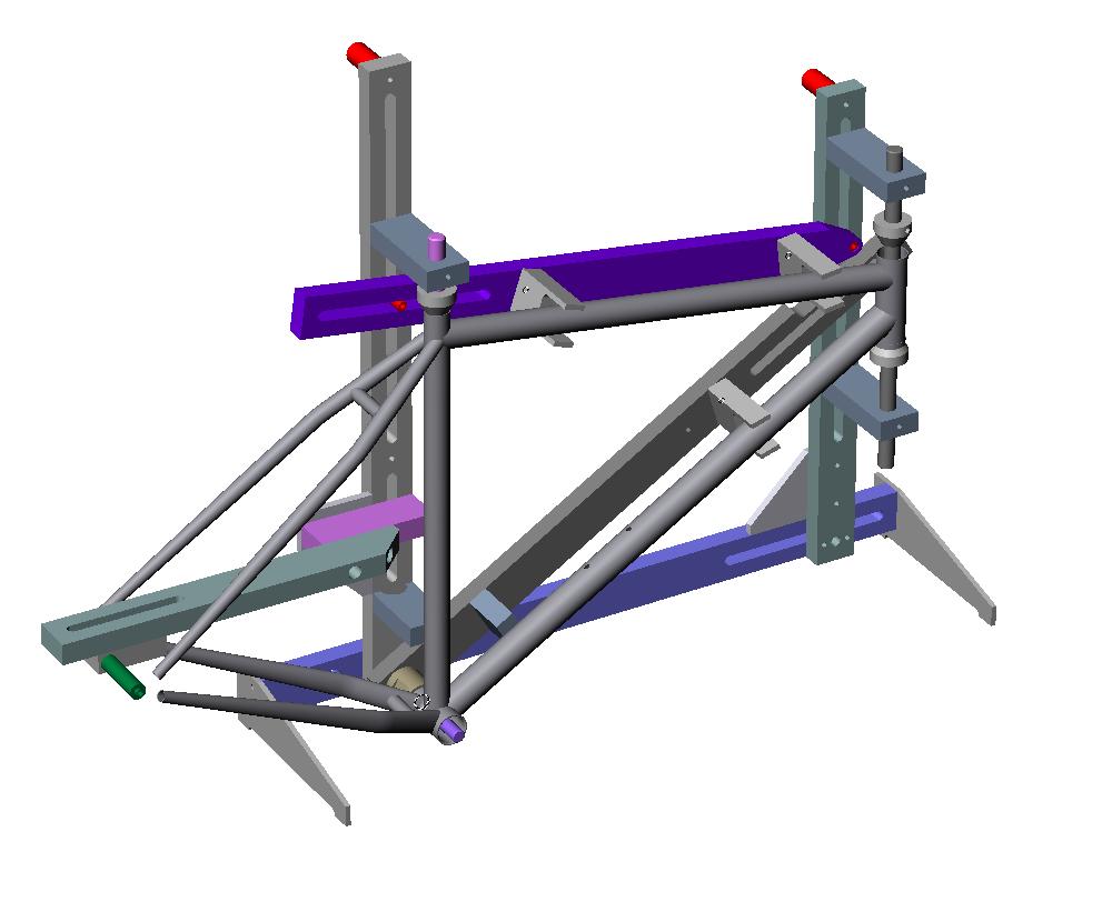
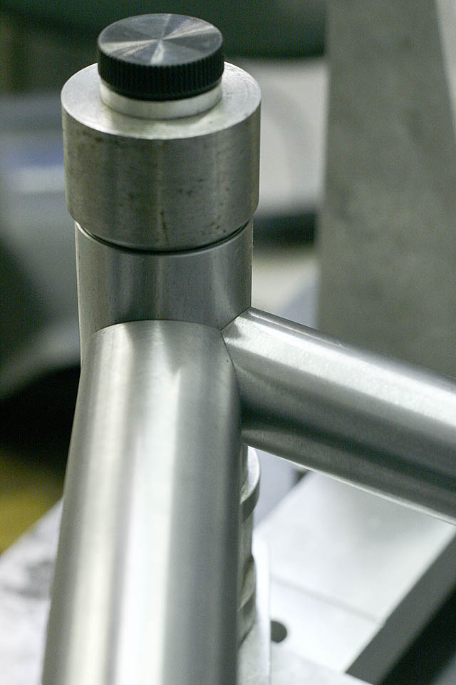
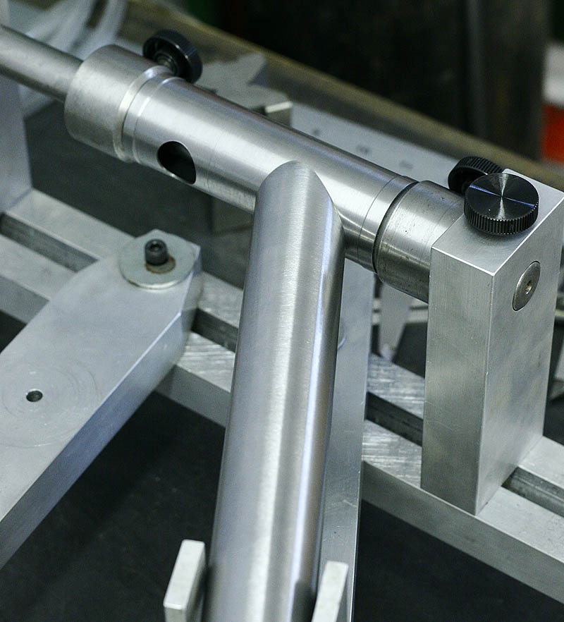
The sanded joints make for very accurate tube intersections and fit into the jig perfectly to maintain exact geometry and post weld straightness.

Tube Cutting


The next step is to lay out the dimensions on the tubes. I use a blue layout spray ink and mark the cuts with a fine scribe. Next I cut the tubes to length with a cut off disc. To miter the tubes I do things a little differently now. I used to use bi-metal hole saws to miter tubes on a lathe using a tube holder in place of the tool post. Now I use a mill based belt sander I built to work with very thin walled True Temper S3 tubes. It makes for very accurate cuts in any diameter required. You just need to make a simple round spindle for each size.

Tube Drawings

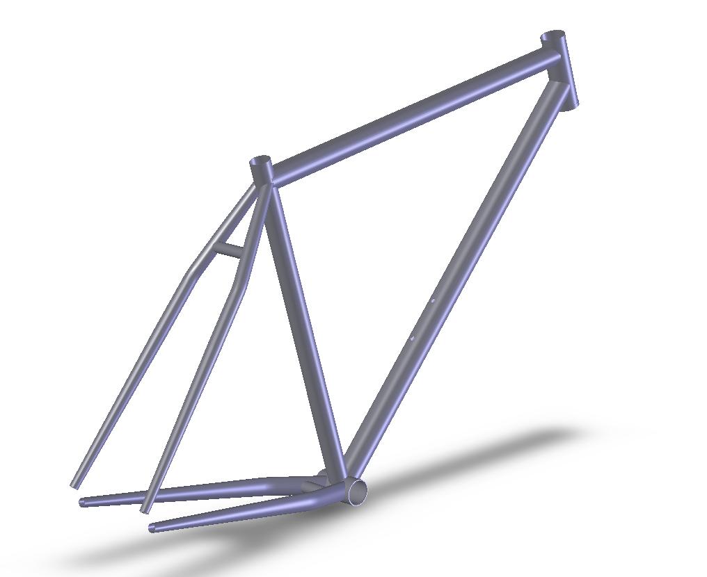
From the CAD model of the frame I make a drawing for each tube and proceed to cutting them to final size etc. These drawings need to created only once per tube (mtb downtube for example). All changes made to the CAD model are automatically reflected in the drawing.

Monday, April 24, 2006

JIG Drawing


The JIG model is used to produce a set up drawing. Once adjusted it is used to position and hold the frame tubes in place for tacking/welding. It only takes a few simple settings to align the JIG.

JIG Model


When I first started building frames I designed and built a frame JIG. The CAD model of the JIG is mated to the frame model and the JIG adjusts itself. From this model comes a drawing that tells me where to set the JIG to fit the tubes for the frame.

Frame Model


Using the frame layout sketch I add appropriate frame tube models. I've previously modelled each tube available from the supplier, in this case True Temper. The tubes are aligned with the lines on the layout sketch and the intersecting between them cut in the CAD model. This creates a model of each individual tube that is linked to a drawing, which i will discuss later.

I also add models of wheels, tires, bars and stem etc to check for clearance.

Frame Layout


The first step I take when building a new frame is to create a CAD drawing of the geometry or in most cases modify an existing CAD file (for a previous frame) to reflect the new geometry. Using this sketch I can capture the required geometry and fit for the rider. I can also check things like toe overlap.

Sunday, April 23, 2006


back40 bicycleworks frame building blog

Over the next little while I will be posting here and documenting the build process I use to construct custom steel bicycle frames. I build as a hobby and have constructed about 20 frames to date. The build blog will chronicle the steps I take in building a 29" wheeled rigid mountain bike frame and fork. Stay tuned for photos and descriptions...